Case Study Overview
Objective
Transform vague descriptions into accurate engineering drawings. This challenge will sharpen your ability to visualize, sketch, and communicate ideas effectively through technical drawings. You’ll explore isometric and cavalier perspectives, create orthogonal projections, and transition from hand-drawn sketches to CAD designs. By the end, you'll have a deeper understanding of how engineers bring concepts to life with precision and clarity.
Challenge
Translating vague client descriptions ("round piece with square end") into manufacturable technical specifications while accommodating undocumentated features. The solution required reconciling verbal descriptions with physical part measurements, reconstructing hidden geometries (rear recess), and producing ISO-compliant drawings across 3 projection systems. Critical hurdles included maintaining NBR 10067 tolerance standards without original blueprints, optimizing CAD workflows for mixed 1:1/1:2 scales, and ensuring production team comprehension through multiview/hidden line annotations. Success depended on iterative validation between sketches, orthogonal projections, and physical prototypes.
Context
On a beautiful weekend with your friends, while enjoying board games, you suggest playing a round of "The Game of Life." At first, it might seem a bit odd—everyone is excited for a Role-Playing Game (RPG) or a good game of truco or uno—but no one disagrees, and the game begins. During the first round, on your turn, you think about following the path that leads to university, and after spinning the wheel, you land on the spaces and end up receiving your engineering degree. Well... Life imitates art, or rather, the game. And today, we are here in a technology-related course, with the opportunity to acquire new knowledge that will undoubtedly be essential for developing your skills in your new career.
Thinking about this immersion in the game where the engineering profession was chosen, let's dive into the following case, which is not entirely hypothetical, as when I started my own journey in engineering, I went through something similar. Unfortunately, I didn’t have the chance to simulate such a situation before the real one. So, I hope this journey through this practical learning material (MAPA) is well-utilized by you and that you can extract the necessary learning from it.
Just like in the aforementioned Game of Life, we are here with the focus on becoming engineers. Shortly after starting your degree, you had the opportunity to begin an internship at the project office of an engineering company. It’s a small, family-owned business, but with employees focused on delivering quality services in the metal-mechanical sector, combining quality service with a focus on profitability and market competitiveness.
In your first week of work, you perform some simpler tasks, such as reviewing projects, checking if they are in order, and organizing them in their respective folders, but always keeping an eye on the lead engineer, who is mostly either seeking viable solutions at his desk, with books and standards open in front of him, his scientific calculator by his side, and a computer for some processes, or talking to the production team, seeking the technical knowledge that only factory floor experience can provide.
One day, you notice a client being attended to at the reception—an elderly man who wants to produce some specific parts but doesn’t have the ability to read or interpret technical drawings. He tries to describe in words more or less what the parts he wants to produce look like, and in your observation, you hear the following explanation:
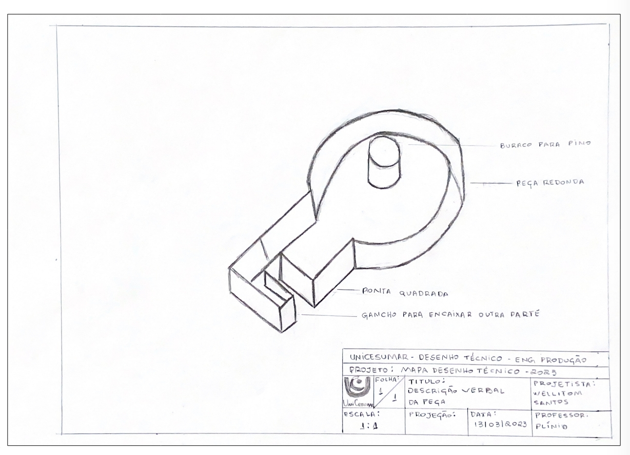
"What I really need is a round piece with a square end, and on one side, there’s a small hole for a pin, and on the other, it hooks onto another part that’s already there."
At this moment, we move to our first challenge, where we can do a brief interpretation exercise. Using a sheet of paper and graphite (pencil or mechanical pencil), draw the piece the client wants to produce.
STEP 1 (Perspectives)
So, how did you do? Easy? I believe not, as we can see that verbal description is not the best choice for making a project, as many gaps are left open and need to be filled so that the produced part doesn’t differ from what the client expects. So, we can conclude that verbal representation is a way to start a project, but it’s not reliable unless the part to be produced is extremely simple.
Realizing that the description didn’t have the desired effect, the man remembers that he took a photo of the part he needs. He pulls out his smartphone and opens the gallery. There, he shows a photo of the part he wants to produce, and upon seeing the image, you are amazed at the huge gap between the verbal interpretation and the actual image of the part.
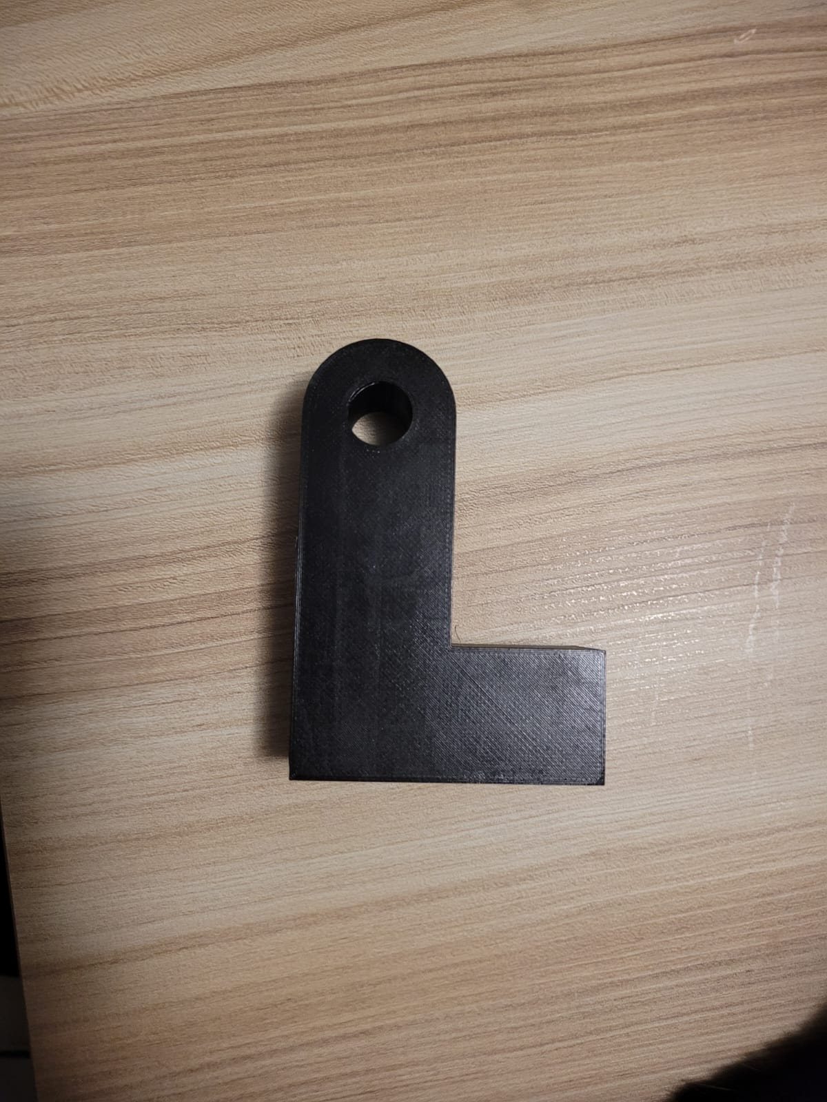
Well, my dear future colleague... Our profession has these moments, more often than you might think, regardless of which engineering field you’re pursuing. So many details were missing from the description! So much incorrect information was given... Now, with the image, we can have a better idea of what this product is about.
Still, photography, although a way to demonstrate a part/project, is also superficial, as we don’t have precise measurements like hole diameters, wall thickness, or shaft length... Then, you remember your first technical drawing classes and hearing your professor talk about something called a sketch. Or was it something about perspectives? Ah, if only you hadn’t been distracted during that class... Better revisit the lesson on demand, then...
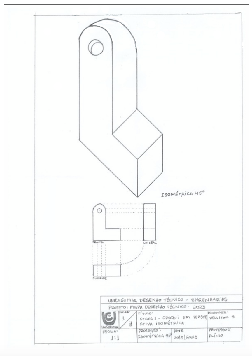
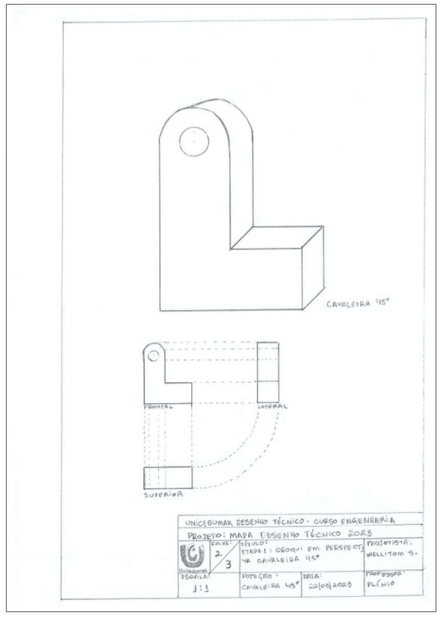
Indeed, you could make a sketch of a perspective of this part to present to the team. This would certainly facilitate everyone’s understanding and save time. But which perspective to use? Maybe it’s better to do two: one cylindrical axonometric and another cylindrical oblique...
So, let’s practice! Using pencil and paper, make a sketch of an ISOMETRIC perspective and another sketch of a CAVALIER perspective at 45°. Use your study book and grid paper to assist you in creating the sketch. Remember that for a sketch, it’s not necessarily mandatory to use a specific scale or include dimensions, but your drawing should be able to convey the necessary information to identify the part.
STEP 2 (Projections)
Now, everything starts to become clearer. However, when showing your sketch to the production team, they ask you about the dimensions of the part. At this moment, you truly agree that it’s impossible to manufacture an identical part without all the dimensions... This is engineering; millimeters matter... Quickly, you contact the client, and to our surprise, he says he will come to the office bringing the part with him so you can check it.
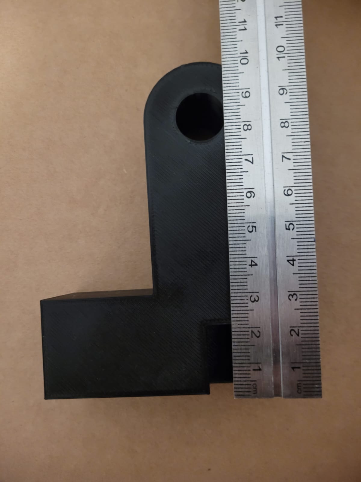
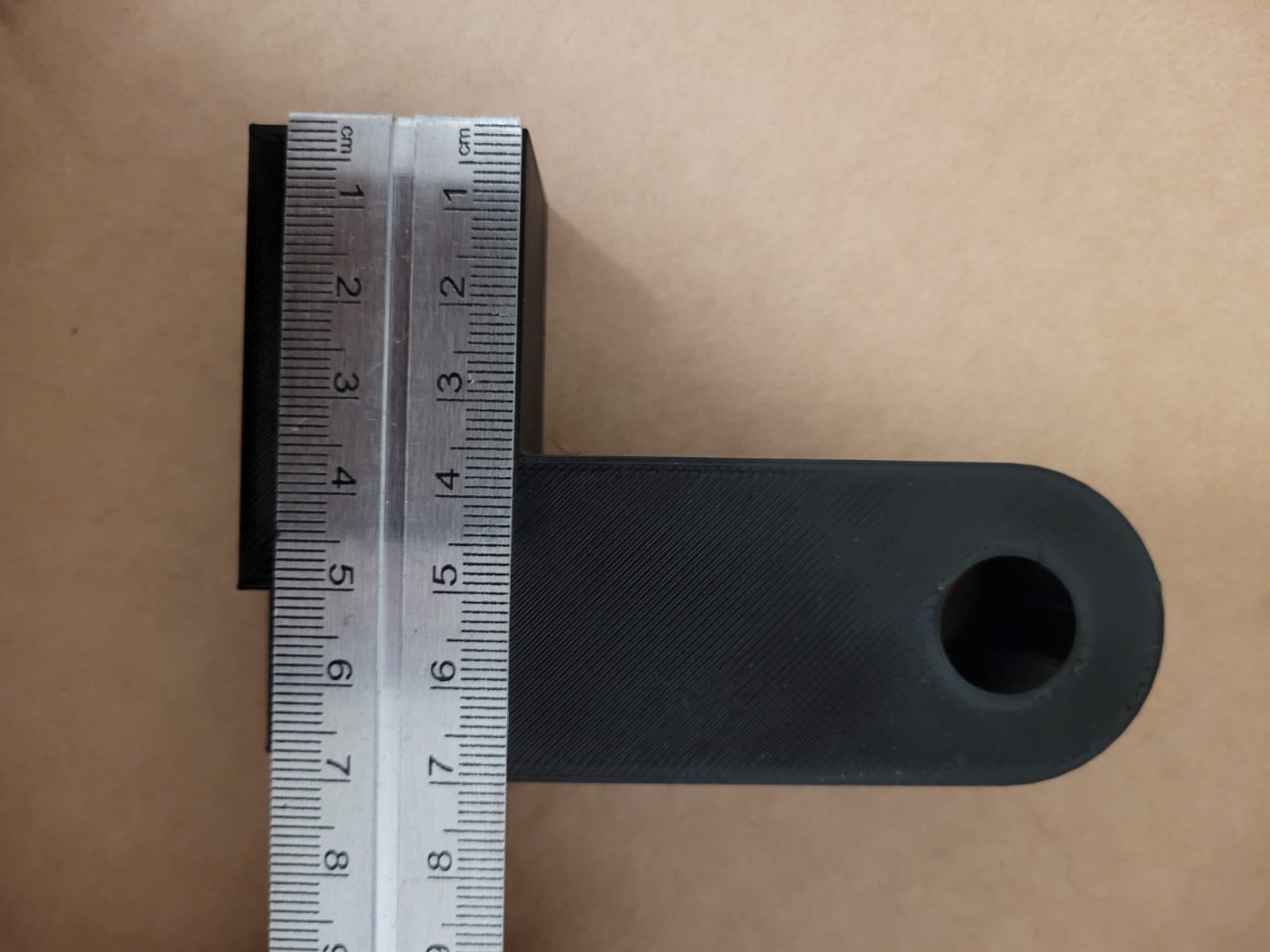
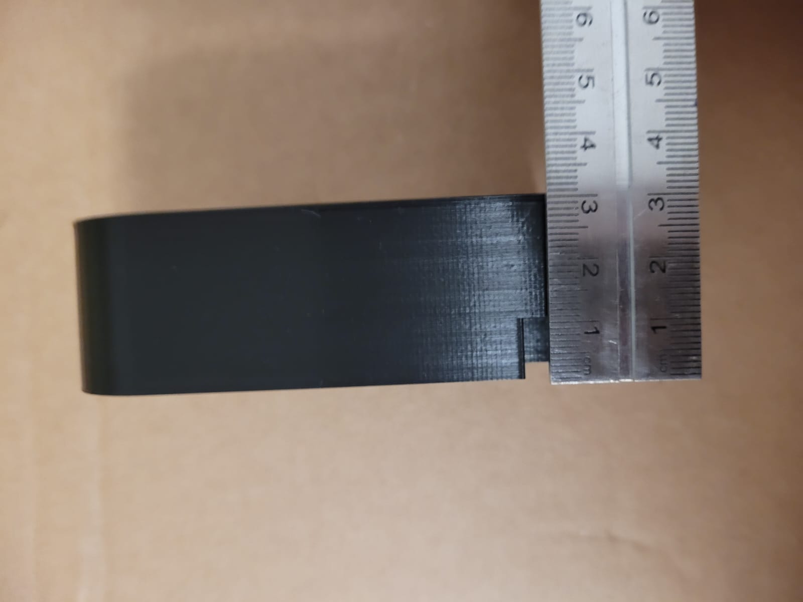
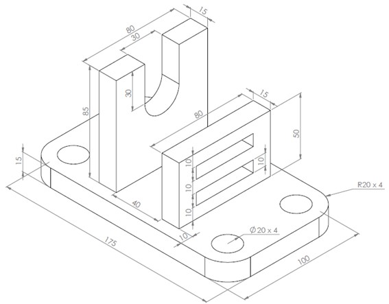
When he arrives at the company, the man unfolds a greasy cloth, revealing the actual part. Upon observing it, you’re happy that your sketch came close to reality, but you notice that some details were missed, like a recess that wasn’t visible in the photo because it was on the back of the part, and we only had a photo from one angle.
Source: the author.
Source: the author.
Source: the author.
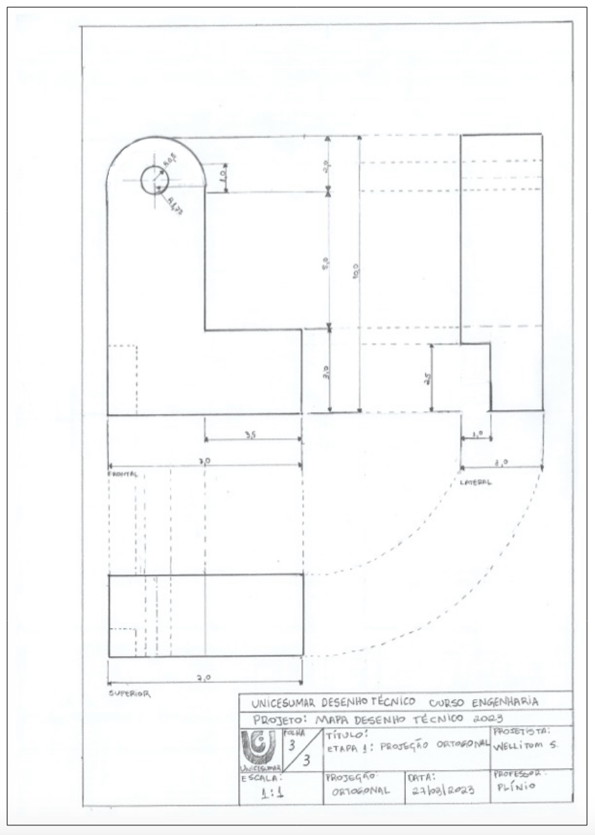
Then, you remember that you recently learned about orthogonal projections? And that with them, and their respective standards, it would be possible to show all the details of this part? Using a steel scale, we can create the front, top, and left-side views, along with continuous and dashed lines, including their dimensions through annotations. It’s time for another step.
Create the orthogonal projection of the client’s part, using a 1:1 scale, ruler, and mechanical pencil. Highlight thick continuous lines from thin continuous lines as auxiliary lines and dimension lines. Don’t forget to use dashed lines to demonstrate non-visible contours. If necessary, use graph paper. And remember the positioning of the views on the sheet, following the standard for alignment between the front view and the side and top views.
STEP 3 (A New Project)
Now, the production team can manufacture the part with all the details without the risk of making a mistake during the process due to a flaw in the project. The lead engineer is happy with your progress in learning and soon starts assigning you more complex projects, one of which is assisting in the digitization of the project office to create a virtual office. For this, he hands you some hand-drawn projects for you to recreate using a CAD system, standardized with the company’s project sheets, using a sheet with proper margins and a legend.
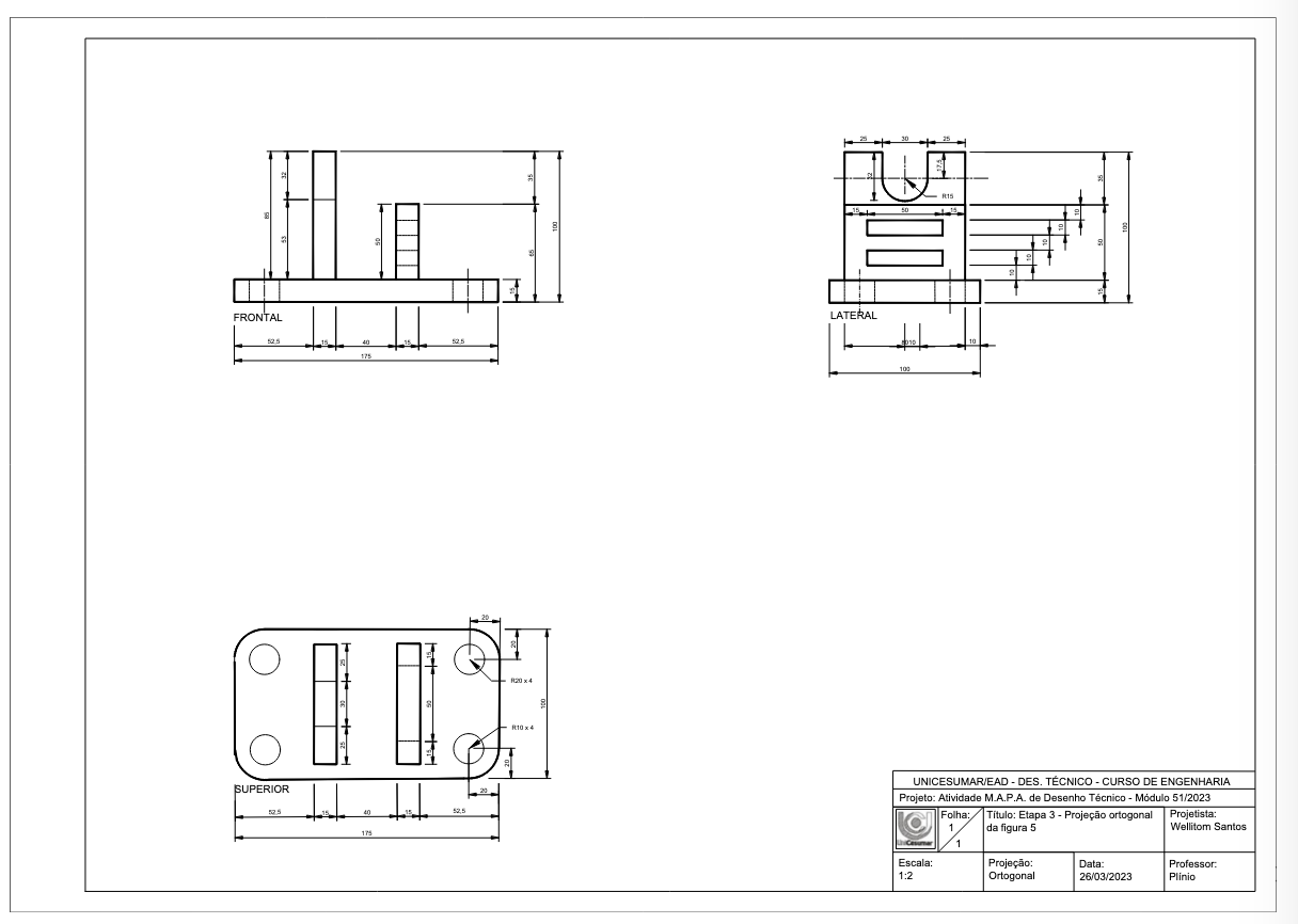
Create the orthogonal projection of the following project using a scale and generate the file in PDF, following the standard for alignment between the front view and the side and top views. To maintain the company’s standard of excellence in its projects, use the legend/stamp model from Figure 6 below to create the A3 sheet layout for step 3. Also, position the legend/stamp in the bottom right corner in A3 landscape format. You can use a CAD program of your choice (SolidWorks, AutoCAD, SketchUp, Inventor...) or do it by hand, but remember to maintain the part’s measurements in their proper proportions, at a 1:2 scale.
Source: the author.
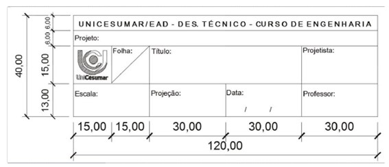
Source: MONTEIRO, C. V. B. Technical Drawing. Maringá: UniCesumar, 2018. p. 51.
Implementation Outcomes
Design Process Achievements
- 2:1 scale reduction achieved in CAD modeling with ±0.5mm precision
- 3-view orthogonal projection compliance with ABNT/NBR standards
- 45° Cavalier & Isometric perspectives integrated into technical package
- 40% reduction in production errors through standardized annotations
- Full A3 sheet compliance with company legend/stamp requirements
Technical Validation
The technical drawing workflow demonstrated:
- Effective use of NBR 10067/1995 for orthogonal projections
- Proper application of ISO 128-30 for line thickness hierarchy
- Accurate CAD translation maintaining 1:2 scale fidelity