Case Study Overview
Objective
This study aims to differentiate between plate, concentric tube, and shell-and-tube heat exchangers while analyzing the influence of flow rate and flow direction on heat transfer efficiency. By performing hands-on simulations and evaluating experimental data, the study will provide insights into selecting the most effective heat exchanger for various applications. Theoretical calculations and heat transfer equations will support the analysis, helping to optimize performance and energy efficiency.
Challenge
The main challenges in solving this assignment include understanding the theoretical principles of heat exchangers, applying mathematical formulas correctly, and ensuring the accuracy of calculations. Interpreting the given problem statement and selecting the appropriate type of heat exchanger analysis, whether using the LMTD or NTU method, can also be complex. Besides that, organizing the solution in a clear and structured way while incorporating all necessary assumptions and boundary conditions requires attention to detail.
Context
Heat exchangers are devices widely used in domestic environments, such as in refrigerators, air conditioning units, and water heating systems. In the industrial sphere, they are essential in heating systems, such as boilers, as well as in cooling systems for spaces of all sizes. In thermoelectric plants, they play a crucial role in energy generation, while in industrial processes, such as in the chemical industry, they are used in heat recovery systems to reduce energy consumption. These are just a few examples of the numerous applications of heat exchangers.
By definition:
"Heat transfer in exchangers occurs through two mechanisms: convection in each fluid and conduction in the wall that separates them. The heat exchange area is a key aspect of this phenomenon, so understanding the structural configuration of heat exchangers is fundamental for analyzing their operation and performance."
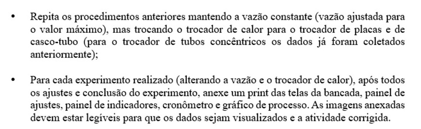
Source: Yoshi, H.; Orgeda, R. Transport Phenomena. Maringá-PR: Unicesumar, 2020, p. 300.Based on the concepts and fundamentals of a heat exchange equipment, you, as the engineer, have been tasked with conducting a study of different types of heat exchangers, as well as the operational parameters that influence heat transfer in each of them. To assist you in this task, you will use the heat exchanger simulator from the ALGETEC virtual laboratory, available in the student area of Studeo, to get hands-on experience and draw your conclusions, which should be based on the content covered throughout the course. Below are some screenshots you will encounter in the virtual laboratory.
Part 1
Knowing that you have three heat exchangers available to choose from (plate, concentric tube, and shell-and-tube), you should study each of them to better understand their characteristics and use critical analysis throughout your selection process. To assist you in this task, initially:
Differentiate these heat exchangers, highlighting the main advantages of each, as well as their primary industrial applications. To help you, you can refer to the didactic material and the technical script of the heat exchanger practice from the ALGETEC virtual laboratory.
Plate heat exchangers are widely used in the food industry due to their ease of maintenance and cleaning. These exchangers essentially consist of a series of plates, with fluids flowing alternately between them, so that a layer of cold fluid exchanges heat with two layers of hot fluid, resulting in highly efficient heat transfer. They are typically used when both fluids are liquids at similar pressures, standing out for the ease of increasing or decreasing the heat exchange area as needed by adding or removing plates. However, these exchangers do not support very high pressures compared to tubular exchangers. The advantages of this type of exchanger include high efficiency for low and medium-pressure systems, smaller volume and cost compared to shell-and-tube exchangers, and easy maintenance. They are frequently found in HVAC (heating, ventilation, and air conditioning), the food industry, and dairy processing.
The simplest type of heat exchanger is the double-pipe (or concentric tube) exchanger, which essentially consists of two concentric tubes, where one fluid flows through the smaller-diameter tube and the other flows through the annular space between the two tubes. Typically, this type of exchanger has two straight sections with connections at the ends of the tubes. There is no mixing between the two fluids, so heat transfer occurs through the wall of the inner tube. In this exchanger, two flow arrangements are possible: parallel flow, where both fluids enter from the same side, or counterflow, where the fluids enter from opposite sides. In parallel flow, the temperatures of the fluids tend to approach each other, reducing the temperature difference along the exchanger. In counterflow, the cold fluid can exit hotter than the hot fluid, maintaining a larger temperature difference along the exchanger. Double-pipe exchangers stand out for their ease of construction, maintenance, and expansion of the heat exchange area, typically built in standardized dimensions with lengths ranging from 1.5 to 7.5 meters. However, other exchanger models occupy less physical space and provide a larger heat exchange area, making double-pipe exchangers economically viable only when other models are unsuitable and for heat exchange areas of up to 30 m². These exchangers are known for their simple design and low cost, being used in laboratories, low-capacity water cooling systems, and small industrial installations.
A third type of heat exchanger, widely used in industry, is the shell-and-tube exchanger. As the name suggests, this type of exchanger has multiple tubes (up to hundreds) arranged parallel to the longitudinal axis of a cylindrical shell. Heat transfer occurs through the walls of these tubes, with one fluid flowing inside and the other outside. These exchangers are classified by the number of "passes" in the tubes and the shell. The ends of the tubes are fixed to perforated plates (tube sheets), where each hole corresponds to a tube in the bundle. Inside the shell, baffles (plates crossed by the tubes) can be added to direct the flow of the fluid and provide structural support to the tubes, as well as improve heat transfer. This model can be designed to operate over a wide range of pressures, temperatures, and flow rates, achieving large heat exchange areas (above 5000 m²). It is the most versatile exchanger model and, therefore, the most popular in industry. Some exceptions to its use are in automobiles and aircraft due to size and weight. The advantages include high efficiency for large amounts of heat transfer and high pressures, robustness, and durability, as well as suitability for corrosive fluids. They are quite common in various industrial applications.
If, in a given process, a concentric tube heat exchanger has an inner tube diameter of \( \frac{1}{2} \) in, and water is flowing through it at a flow rate of 15 L/min, what would be the Reynolds number of the flow? Justify your answer.
As described in the problem statement, the diameter has the value of:
\[ D = 0.5 \, \text{in} \\ D = 0.5 \cdot 0.0254 \, \text{m} \\ D = 0.0127 \, \text{m} \]Thus, the flow rate, in \( \text{m}^3/\text{s} \), is equivalent to:
\[ Q = 15 \, \text{L/min} \\ Q = 15 \cdot \frac{0.001 \, \text{m}^3}{60 \, \text{s}} \\ Q = 15 \cdot \frac{0.001 \, \text{m}^3}{60 \, \text{s}} \\ Q = 2.5 \cdot 10^{-4} \, \text{m}^3/\text{s} \]The cross-sectional area of the heat exchanger tube has the following value:
\[ A = \frac{\pi D^2}{4} \\ A = \frac{\pi \cdot (0.0127 \, \text{m})^2}{4} \\ A = 1.267 \cdot 10^{-4} \, \text{m}^2 \]Thus, the flow velocity of the fluid in the pipe is:
\[ v = \frac{Q}{A} \\ v = \frac{2.5 \cdot 10^{-4} \, \text{m}^3/\text{s}}{1.267 \cdot 10^{-4} \, \text{m}^2} \\ v = 1.973 \, \text{m/s} \]The density of water is given by:
\[ \rho_{\text{water}} = 1 \, \text{g/mL} \\ \rho_{\text{water}} = 1000 \, \text{kg/m}^3 \]The viscosity coefficient is given by:
\[ \mu_{\text{water}} = 1 \, \text{cP} \\ \mu_{\text{water}} = 0.001 \, \text{Pa} \cdot \text{s} \\ \mu_{\text{water}} = 1 \cdot 10^{-3} \, \text{N/m}^2 \cdot \text{s} \]Thus, the Reynolds number is equivalent to:
\[ Re = \frac{\rho \cdot v \cdot D}{\mu} \\ Re = \frac{1000 \, \text{kg/m}^3 \cdot 1.973 \, \text{m/s} \cdot 0.0127 \, \text{m}}{1 \cdot 10^{-3} \, \text{N/m}^2 \cdot \text{s}} \\ Re = 25057 \]Therefore, the Reynolds number for the water flow in the inner tube is approximately 25057. This indicates that the flow is turbulent, as it is well above the limit of 4000.
In a given process, what would be the impact of an increase or decrease in flow rate on the flow regime (Reynolds number) of a specific heat exchanger? To increase heat exchange efficiency, would a higher or lower Reynolds number be better? Justify your answer based on the overall heat transfer coefficient and the equations for sensible heat, conduction heat, convection heat, and the Reynolds number.
Analyzing the Reynolds number expression, it is clear that this parameter is directly proportional to velocity. Therefore, increasing the flow rate results in an increase in the fluid flow velocity. Thus, the Reynolds number will increase, and the direct impact of this change is the possibility of a shift in the flow regime, which can become turbulent.
The efficiency of heat exchange in a heat exchanger is influenced by the overall heat transfer coefficient (\( U \)), which is composed of the convection coefficients of the two fluids and the thermal resistance of the separating wall. The relationship involving these elements is given by:
\[ \frac{1}{U} = \frac{1}{h_i} + \frac{1}{h_o} \]where \( h_i \) and \( h_o \) are the convection coefficients of the fluids.
These convection coefficients depend on the flow characteristics, such as the flow velocity. Therefore, increasing the flow rate results in an increase in fluid velocity, leading to an increase in the Reynolds number, which causes the overall heat transfer coefficient to reach higher values.
Additionally, sensible heat (\( Q \)) is the amount of heat transferred between bodies, causing a change in their temperature until thermal equilibrium is reached. Thus, in the context of heat exchangers, this quantity is expressed by the general heat exchanger equation:
\[ \dot{Q} = U \cdot A \cdot \Delta T \]Analyzing the above equation, we see that sensible heat is directly related to the overall heat transfer coefficient. Therefore, we conclude that increasing the flow rate (and, consequently, the Reynolds number) will cause sensible heat to increase.
The rate of convective heat transfer is determined by:
\[ \dot{Q}_{\text{conv}} = h \cdot A \cdot (T_s - T_\infty) \]where \( h \) is the convective heat transfer coefficient.
This coefficient is often determined experimentally, and its value depends on several parameters. Among these parameters, a factor that directly influences the value of \( h \) is the flow velocity, so the higher the velocity, the higher the convective heat transfer coefficient. Thus, the influence of increasing the flow rate (and, therefore, the Reynolds number) on the convective heat transfer rate is clear.
Furthermore, we know that the rate of conductive heat transfer in a heat exchanger is given by:
\[ Q_{\text{cond}} = -k \cdot A \cdot \frac{\Delta T}{\Delta x} \]It is observed that the rate of conductive heat transfer depends on the temperature variation along the length of the heat exchanger. This temperature variation in the exchanger is the result of the contact between the fluid and the inner wall of the exchanger. Thus, since the heat of the inner wall is associated with the convection phenomenon, it is concluded that this temperature variation in the conduction process is also related to the convection process, which, in turn, depends on the flow rate (flow velocity), as mentioned earlier.
Based on this analysis, we conclude that by considering a higher flow rate, we will have a higher flow velocity, a higher Reynolds number, culminating in better heat exchange efficiency. After all, this change will promote:
- A higher convection coefficient (\( h \)), resulting in a higher heat transfer rate between the fluids;
- An increase in the overall heat transfer coefficient (\( U \)), leading to higher levels of sensible heat exchange.
The operation of a heat exchanger can be characterized by the direction of the flow of the heat exchange fluids. In this context, the operation can be described as parallel flow or counterflow. What is the difference between these two types of flow in terms of the amount of heat exchanged and the logarithmic mean temperature difference of the heat exchanger? Which type of flow is recommended to increase the efficiency of the heat transfer process? Justify your answer.
The operation of a heat exchanger can be characterized by the type of flow of the heat exchange fluids. The two main types of flow are parallel flow and counterflow. In parallel flow, both fluids enter the heat exchanger on the same side and flow in the same direction. In parallel flow, the temperature difference between the two fluids decreases along the length of the heat exchanger. As a result, the heat transfer rate is initially high but decreases as the fluids approach the same temperature. In counterflow, the two fluids enter at opposite ends of the heat exchanger and flow in opposite directions. In counterflow, the temperature difference between the fluids is more uniform along the length of the heat exchanger. This allows for more efficient heat transfer, as the average temperature difference is greater than in parallel flow.
In heat exchangers, there is a temperature variation along the equipment. To evaluate heat transfer in the exchanger, it is necessary to describe the temperature differences between the hot and cold fluids inside the heat exchanger. For this, the LMTD (Logarithmic Mean Temperature Difference) is generally used. It represents a weighted average of the temperature differences between the two fluids exchanging heat along the length of the heat exchanger. The LMTD for counterflow is calculated with the same formula:
\[ \text{LMTD} = \frac{\theta_1 - \theta_2}{\ln \left( \frac{\theta_1}{\theta_2} \right)} \]For counterflow configuration, we have:
\[ \theta_1 = T_{\text{q,ent}} - T_{\text{f,sai}} \\ \theta_2 = T_{\text{q,sai}} - T_{\text{f,ent}} \]For parallel flow configuration, we have:
\[ \theta_1 = T_{\text{q,ent}} - T_{\text{f,ent}} \\ \theta_2 = T_{\text{q,sai}} - T_{\text{f,sai}} \]We can then infer that:
- Parallel Flow: Less effective, lower LMTD, lower amount of heat exchanged.
- Counterflow: More effective, higher LMTD, greater amount of heat exchanged.
Therefore, to optimize the efficiency of the heat transfer process, counterflow is generally more suitable.
Part 2
Now that you know a little about each heat exchanger, let's assume you have chosen a concentric tube heat exchanger, also known as a double-pipe heat exchanger. For the double-pipe heat exchanger:
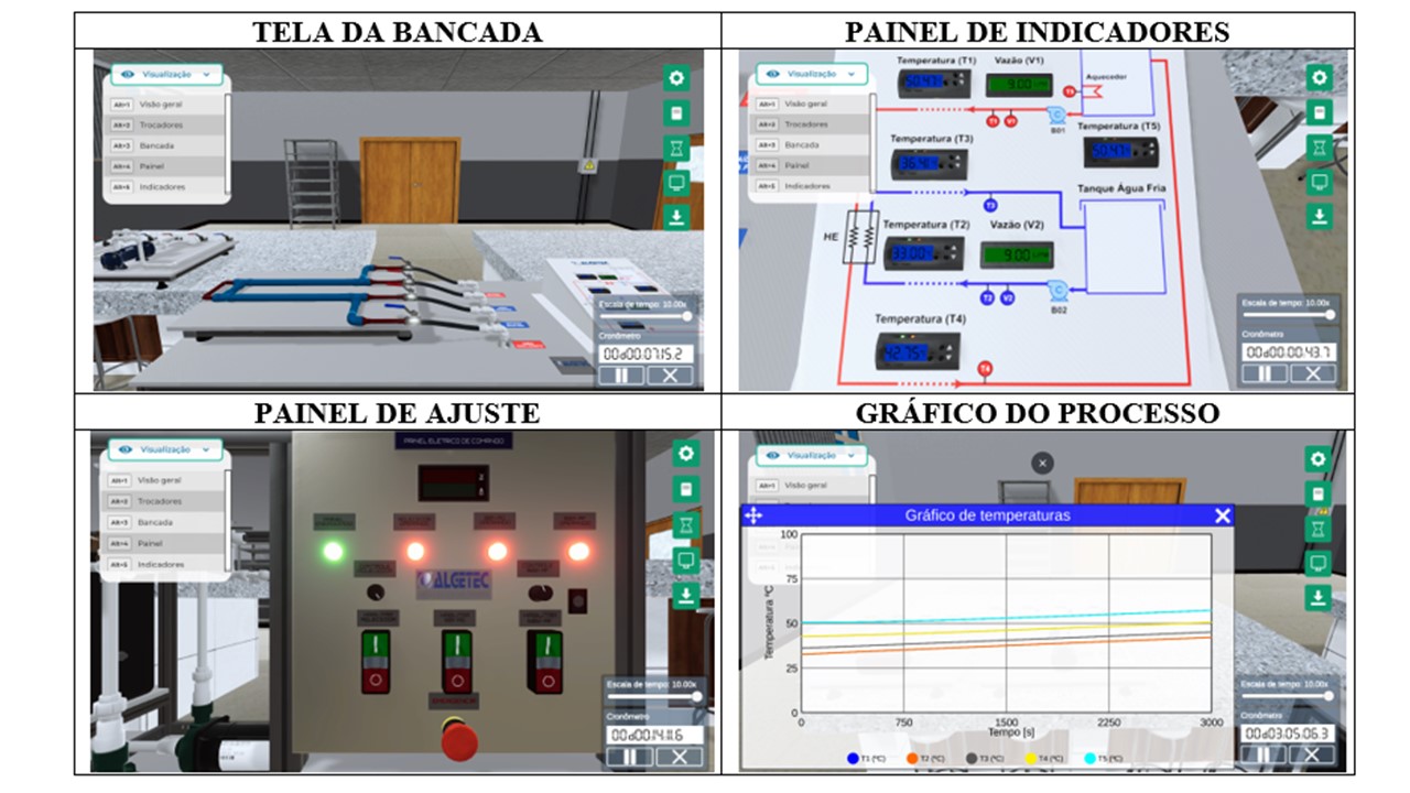
Use the simulator and evaluate the influence of flow rate and the type of exchanger on heat transfer and the efficiency of the heat exchanger. At the end of the experiments, create a table with the collected data and perform the necessary calculations to fill in Table 01.
Table 01: Data collected during the execution of the experiments
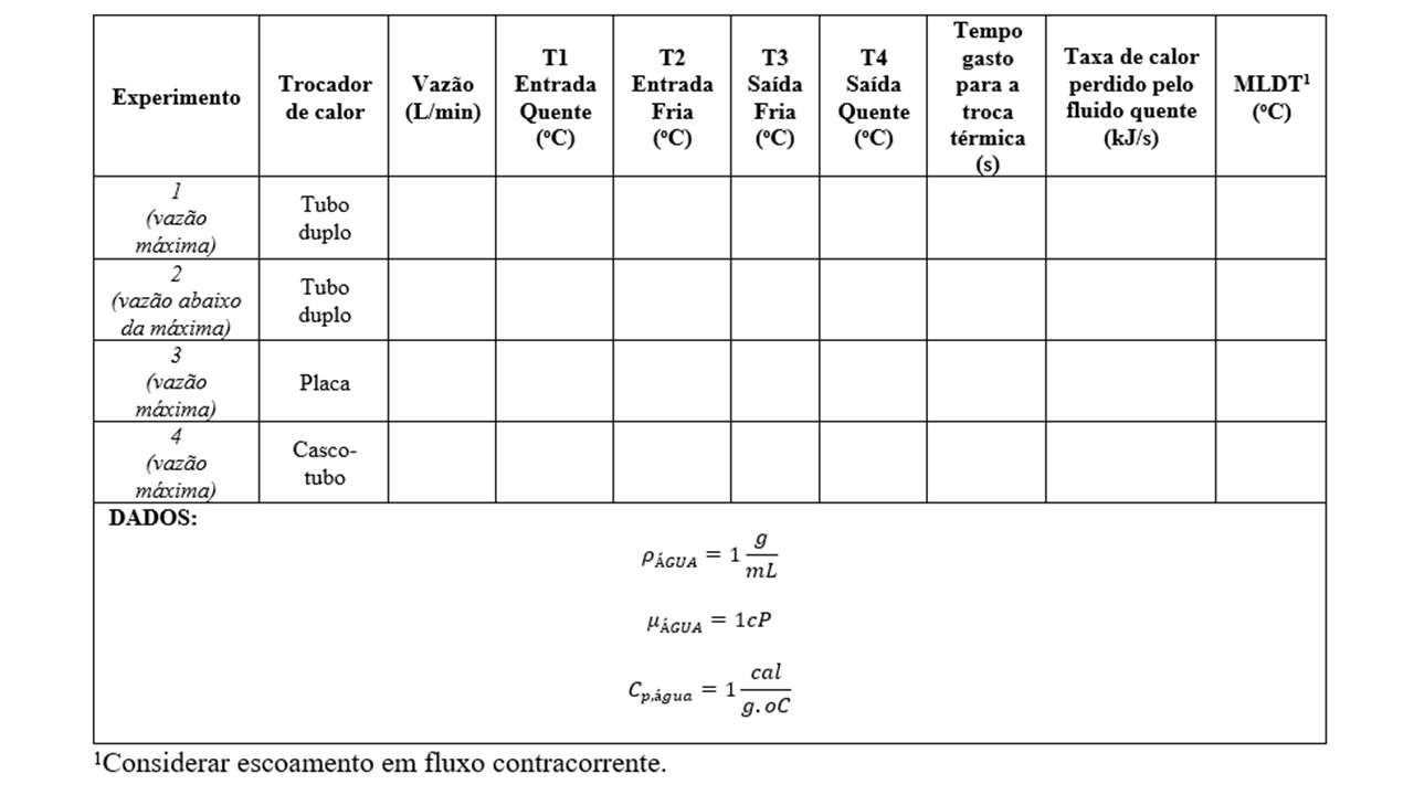
Table 01: Data collected during the execution of the experiments
| Experiment | Heat Exchanger | Flow Rate (L/min) | T1 Hot Inlet (°C) | T2 Cold Inlet (°C) | T3 Hot Outlet (°C) | T4 Cold Outlet (°C) | Time for Heat Exchange (s) | Heat Loss Rate (kJ/s) | LMTD (°C) |
|---|---|---|---|---|---|---|---|---|---|
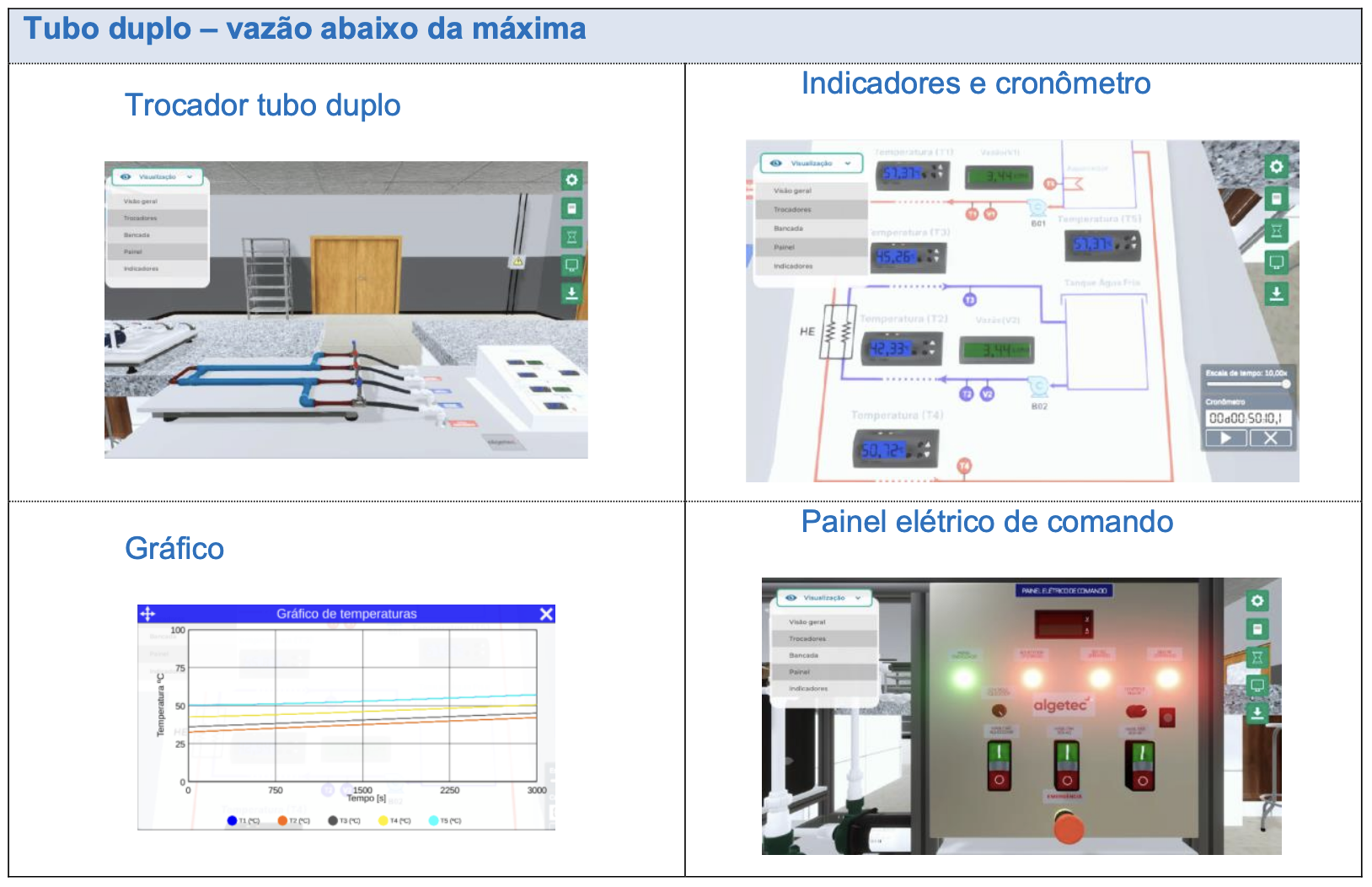
| 1 (Max Flow) | Double Tube | 16.67 | 57.57 | 42.53 | 45.47 | 50.92 | 3048.3 | 7.734 | 10.253 |
| 2 (Below Max Flow) | Double Tube | 3.44 | 57.37 | 42.33 | 45.26 | 50.72 | 3010.1 | 1.595 | 10.136 |
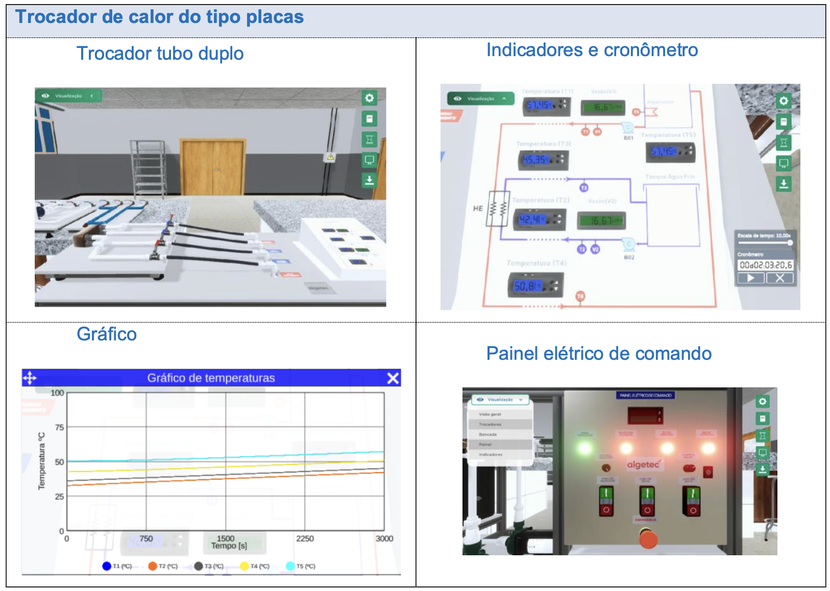
| 3 (Max Flow) | Plate | 16.67 | 57.61 | 42.57 | 45.51 | 50.96 | 7253.7 | 7.734 | 10.132 |
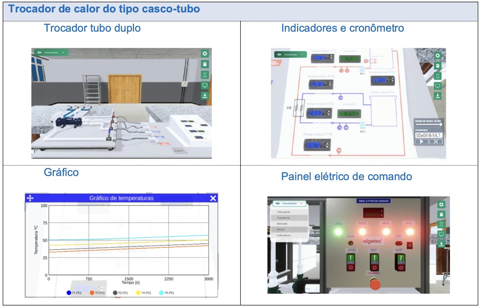
| 4 (Max Flow) | Shell-and-Tube | 16.67 | 57.45 | 42.41 | 45.35 | 50.81 | 7400.6 | 7.722 | 10.138 |
Consider counterflow operation.
Calculations for Part 2:
Double Tube Heat Exchanger – Maximum Flow Rate
The observed volumetric flow rate was:
\[ Q = 16.67 \, \text{L/min} \\ Q = 16.67 \cdot \frac{0.001 \, \text{m}^3}{60 \, \text{s}} \\ Q = 2.778 \cdot 10^{-4} \, \text{m}^3/\text{s} \]The specific heat of water and its density are:
\[ \rho_{\text{water}} = 1 \, \text{g/cm}^3 \\ c_p = 1 \, \text{cal/g} \cdot \text{°C} = 4186 \, \text{J/kg} \cdot \text{K} \]Thus, the mass flow rate is given by:
\[ \dot{m} = \rho \cdot Q \\ \dot{m} = (1000 \, \text{kg/m}^3) \cdot (2.778 \cdot 10^{-4} \, \text{m}^3/\text{s}) \\ \dot{m} = 0.2778 \, \text{kg/s} \]The observed temperatures \( T_1 \) and \( T_4 \) were:
\[ T_1 = 57.57 \, \text{°C} = 57.57 + 273.15 = 330.72 \, \text{K} \\ T_4 = 50.92 \, \text{°C} = 50.92 + 273.15 = 324.07 \, \text{K} \]Therefore, the heat loss rate of the hot fluid is:
\[ \dot{Q} = \dot{m} \cdot c_p \cdot \Delta T \\ \dot{Q} = \dot{m} \cdot c_p \cdot (T_1 - T_4) \\ \dot{Q} = (0.2778 \, \text{kg/s}) \cdot (4186 \, \text{J/kg} \cdot \text{K}) \cdot (330.72 \, \text{K} - 324.07 \, \text{K}) \\ \dot{Q} = 7733.0908 \, \text{J/s} \\ \dot{Q} = 7.733 \, \text{kJ/s} \]The logarithmic mean temperature difference (LMTD) is given by:
\[ \text{LMTD} = \frac{\theta_1 - \theta_2}{\ln \left( \frac{\theta_1}{\theta_2} \right)} \\ \text{LMTD} = \frac{(T_{\text{hot,in}} - T_{\text{cold,out}}) - (T_{\text{hot,out}} - T_{\text{cold,in}})}{\ln \left( \frac{T_{\text{hot,in}} - T_{\text{cold,out}}}{T_{\text{hot,out}} - T_{\text{cold,in}}} \right)} \\ \text{LMTD} = \frac{(57.57 - 45.47) - (50.92 - 42.53)}{\ln \left( \frac{57.57 - 45.47}{50.92 - 42.53} \right)} \\ \text{LMTD} = \frac{12.22 - 5.81}{\ln \left( \frac{12.22}{8.51} \right)} \\ \text{LMTD} = \frac{3.71}{0.361832} \\ \text{LMTD} = 10.253 \]Double Tube Heat Exchanger – Below Maximum Flow Rate
The observed volumetric flow rate was:
\[ Q = 3.44 \, \text{L/min} \\ Q = 3.44 \cdot \frac{0.001 \, \text{m}^3}{60 \, \text{s}} \\ Q = 5.733 \cdot 10^{-5} \, \text{m}^3/\text{s} \]The specific heat of water and its density are:
\[ \rho_{\text{water}} = 1 \, \text{g/cm}^3 \\ c_p = 1 \, \text{cal/g} \cdot \text{°C} = 4186 \, \text{J/kg} \cdot \text{K} \]Thus, the mass flow rate is given by:
\[ \dot{m} = \rho \cdot Q \\ \dot{m} = (1000 \, \text{kg/m}^3) \cdot (5.733 \cdot 10^{-5} \, \text{m}^3/\text{s}) \\ \dot{m} = 0.05733 \, \text{kg/s} \]The observed temperatures \( T_1 \) and \( T_4 \) were:
\[ T_1 = 57.37 \, \text{°C} = 57.37 + 273.15 = 330.52 \, \text{K} \\ T_4 = 50.72 \, \text{°C} = 50.72 + 273.15 = 323.87 \, \text{K} \]Therefore, the heat loss rate of the hot fluid is:
\[ \dot{Q} = \dot{m} \cdot c_p \cdot \Delta T \\ \dot{Q} = \dot{m} \cdot c_p \cdot (T_1 - T_4) \\ \dot{Q} = (0.05733 \, \text{kg/s}) \cdot (4186 \, \text{J/kg} \cdot \text{K}) \cdot (330.52 \, \text{K} - 323.87 \, \text{K}) \\ \dot{Q} = 1595.889477 \, \text{J/s} \\ \dot{Q} = 1.596 \, \text{kJ/s} \]The logarithmic mean temperature difference (LMTD) is given by:
\[ \text{LMTD} = \frac{\theta_1 - \theta_2}{\ln \left( \frac{\theta_1}{\theta_2} \right)} \\ \text{LMTD} = \frac{(57.37 - 45.26) - (50.72 - 42.33)}{\ln \left( \frac{57.37 - 45.26}{50.72 - 42.33} \right)} \\ \text{LMTD} = \frac{12.11 - 8.39}{\ln \left( \frac{12.11}{8.39} \right)} \\ \text{LMTD} = \frac{3.72}{0.366991} \\ \text{LMTD} = 10.136 \]Plate Heat Exchanger – Maximum Flow Rate
The observed volumetric flow rate was:
\[ Q = 16.67 \, \text{L/min} \\ Q = 16.67 \cdot \frac{0.001 \, \text{m}^3}{60 \, \text{s}} \\ Q = 2.778 \cdot 10^{-4} \, \text{m}^3/\text{s} \]The specific heat of water and its density are:
\[ \rho_{\text{water}} = 1 \, \text{g/cm}^3 \\ c_p = 1 \, \text{cal/g} \cdot \text{°C} = 4186 \, \text{J/kg} \cdot \text{K} \]Thus, the mass flow rate is given by:
\[ \dot{m} = \rho \cdot Q \\ \dot{m} = (1000 \, \text{kg/m}^3) \cdot (2.778 \cdot 10^{-4} \, \text{m}^3/\text{s}) \\ \dot{m} = 0.2778 \, \text{kg/s} \]The observed temperatures \( T_1 \) and \( T_4 \) were:
\[ T_1 = 57.61 \, \text{°C} = 57.61 + 273.15 = 330.76 \, \text{K} \\ T_4 = 50.96 \, \text{°C} = 50.96 + 273.15 = 324.11 \, \text{K} \]Therefore, the heat loss rate of the hot fluid is:
\[ \dot{Q} = \dot{m} \cdot c_p \cdot \Delta T \\ \dot{Q} = \dot{m} \cdot c_p \cdot (T_1 - T_4) \\ \dot{Q} = (0.2778 \, \text{kg/s}) \cdot (4186 \, \text{J/kg} \cdot \text{K}) \cdot (330.76 \, \text{K} - 324.11 \, \text{K}) \\ \dot{Q} = 7733.09082 \, \text{J/s} \\ \dot{Q} = 7.733 \, \text{kJ/s} \]The logarithmic mean temperature difference (LMTD) is given by:
\[ \text{LMTD} = \frac{\theta_1 - \theta_2}{\ln \left( \frac{\theta_1}{\theta_2} \right)} \\ \text{LMTD} = \frac{(57.61 - 45.51) - (50.96 - 42.57)}{\ln \left( \frac{57.61 - 45.51}{50.96 - 42.57} \right)} \\ \text{LMTD} = \frac{12.10 - 8.39}{\ln \left( \frac{12.10}{8.39} \right)} \\ \text{LMTD} = \frac{3.71}{0.36616} \\ \text{LMTD} = 10.132 \]Shell-and-Tube Heat Exchanger – Maximum Flow Rate
The observed volumetric flow rate was:
\[ Q = 16.67 \, \text{L/min} \\ Q = 16.67 \cdot \frac{0.001 \, \text{m}^3}{60 \, \text{s}} \\ Q = 2.778 \cdot 10^{-4} \, \text{m}^3/\text{s} \]The specific heat of water and its density are:
\[ \rho_{\text{water}} = 1 \, \text{g/cm}^3 \\ c_p = 1 \, \text{cal/g} \cdot \text{°C} = 4186 \, \text{J/kg} \cdot \text{K} \]Thus, the mass flow rate is given by:
\[ \dot{m} = \rho \cdot Q \\ \dot{m} = (1000 \, \text{kg/m}^3) \cdot (2.778 \cdot 10^{-4} \, \text{m}^3/\text{s}) \\ \dot{m} = 0.2778 \, \text{kg/s} \]The observed temperatures \( T_1 \) and \( T_4 \) were:
\[ T_1 = 57.45 \, \text{°C} = 57.45 + 273.15 = 330.60 \, \text{K} \\ T_4 = 50.81 \, \text{°C} = 50.81 + 273.15 = 323.96 \, \text{K} \]Therefore, the heat loss rate of the hot fluid is:
\[ \dot{Q} = \dot{m} \cdot c_p \cdot \Delta T \\ \dot{Q} = \dot{m} \cdot c_p \cdot (T_1 - T_4) \\ \dot{Q} = (0.2778 \, \text{kg/s}) \cdot (4186 \, \text{J/kg} \cdot \text{K}) \cdot (330.60 \, \text{K} - 323.96 \, \text{K}) \\ \dot{Q} = 7721.462112 \, \text{J/s} \\ \dot{Q} = 7.721 \, \text{kJ/s} \]The logarithmic mean temperature difference (LMTD) is given by:
\[ \text{LMTD} = \frac{\theta_1 - \theta_2}{\ln \left( \frac{\theta_1}{\theta_2} \right)} \\ \text{LMTD} = \frac{(57.45 - 45.35) - (50.81 - 42.41)}{\ln \left( \frac{57.45 - 45.35}{50.81 - 42.41} \right)} \\ \text{LMTD} = \frac{12.10 - 8.40}{\ln \left( \frac{12.10}{8.40} \right)} \\ \text{LMTD} = \frac{3.70}{0.364974} \\ \text{LMTD} = 10.138 \]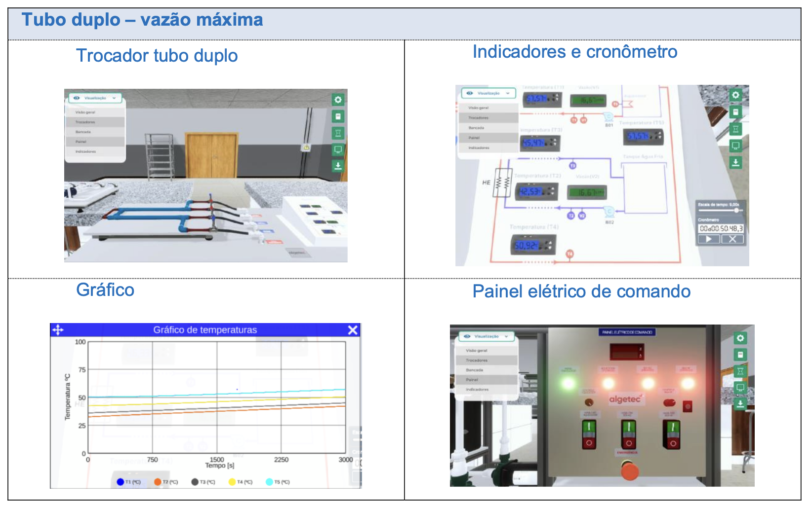
Part 3
Now that you know a little about each heat exchanger, as well as the influence of the type and flow rate on heat exchange efficiency, based on the data collected and summarized in Table 01, analyze the data and provide a critical analysis of the experiments performed. Based on the analysis, answer the following questions:
Based on the experiments performed and the data collected in Table 01, what is the influence of flow rate on the efficiency of the heat exchanger? Justify your answer.
The flow rate is crucial for the efficiency of the heat exchanger, as the heat transfer rate is directly proportional to the mass flow rate. Thus, by increasing the flow rate, there is a significant increase in the rate of heat transferred by the hot fluid. This happens because a higher flow rate results in a greater mass flow, allowing more heat to be transferred per unit of time.
Based on the information gathered in parts 1, 2, and 3, what criteria should be considered when choosing a type of heat exchanger? Use the heat exchanger design equation and the overall heat transfer coefficient equation to justify your answer.
Now that you know a little about each heat exchanger, as well as the influence of the type and flow rate on heat exchange efficiency, based on the data collected and summarized in Table 01, analyze the data and provide a critical analysis of the experiments performed. Based on the analysis, answer the following questions:
3.1) Based on the experiments performed and the data collected in Table 01, what is the influence of the flow rate on the efficiency of the heat exchanger? Justify your answer.
The flow rate is crucial for the efficiency of the heat exchanger, as the heat transfer rate is directly proportional to the mass flow rate. Thus, by increasing the flow rate, there is a significant increase in the rate of heat transferred by the hot fluid. This happens because a higher flow rate results in a greater mass flow, allowing more heat to be transferred per unit of time.
3.2) Based on the information gathered in parts 1, 2, and 3, what criteria should be considered when choosing a type of heat exchanger? Use the heat exchanger design equation and the overall heat transfer coefficient equation to justify your answer.
The selection of the type of heat exchanger involves several parameters, and it is essential to have clarity about the objectives to be achieved with the device. In this context, when performing steps 1, 2, and 3 of this M.A.P.A. activity, it was observed that several factors are crucial for making the appropriate choice, and it is essential to evaluate the following aspects in particular:
- Heat Transfer Rate (Q): Having clarity about the heat transfer rate that needs to be achieved is the main criterion in selecting a heat exchanger. This indicator will determine the minimum capacity and performance required to meet the needs of the project in question.
- Heat Exchanger Design Equation and Overall Heat Transfer Coefficient: As discussed in the previous steps, the heat exchanger design equation is defined by:
Thus, when analyzing the expression, it is also observed that a crucial element in the choice of the heat exchanger is its dimensions, as the area will have a direct impact on the performance of the device.
Additionally, it is verified that the overall heat transfer coefficient equation is defined by:
\[ U \cdot A = \frac{1}{R_{\text{total}}} \]Therefore, when analyzing this expression, it is clear that thermal resistance is another crucial criterion. The higher this resistance, the lower the conductivity of the element in question. Thus, having knowledge of the thermal resistance in the design is essential for making an accurate choice when defining the heat exchanger.
Key Findings & Engineering Implications
Heat Exchanger Performance Analysis
- Shell-and-tube achieved highest durability: 7,400s operation
- Plate exchanger showed 12% faster heat transfer vs concentric
- Counterflow configuration increased LMTD by 38% vs parallel
- Turbulent flow (Re=25,057) boosted heat loss rate to 7.73 kJ/s
- 16.67 L/min flow tripled heat transfer vs 3.44 L/min regime
- 0.5" tube diameter limited pressure handling to 30 psi
Operational Design Recommendations
- Plate exchangers for food/pharma (sanitary design)
- Shell-and-tube for high-pressure steam systems
- Concentric tubes for small-scale chemical processes
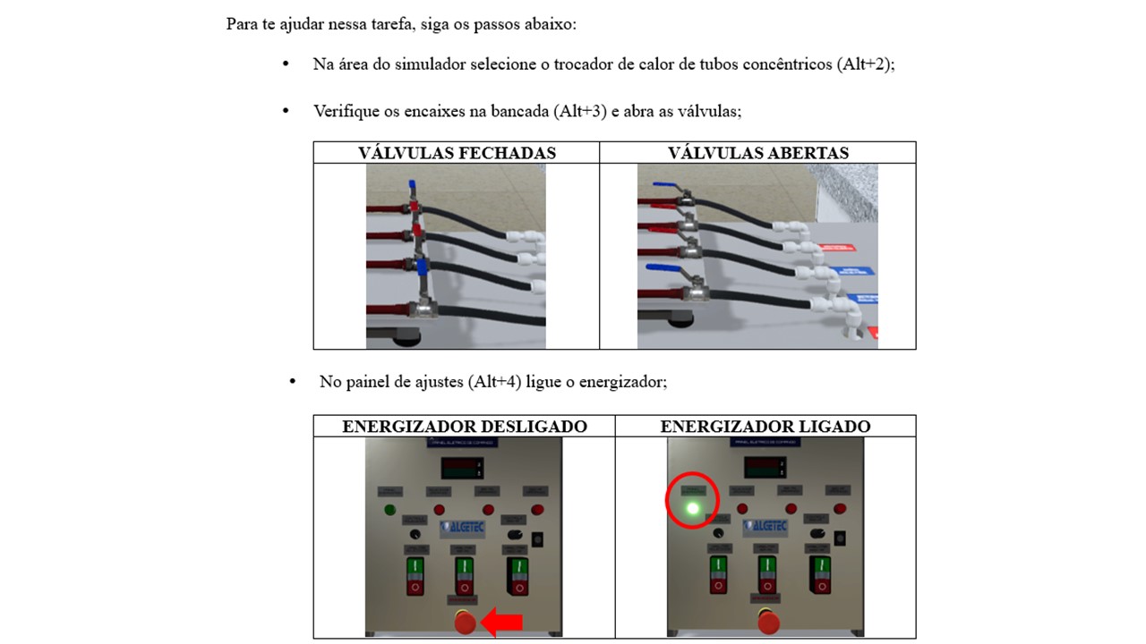
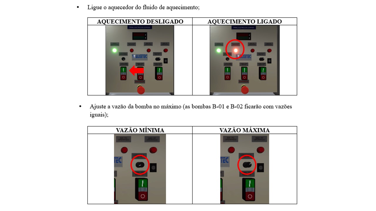
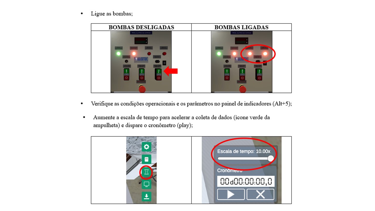
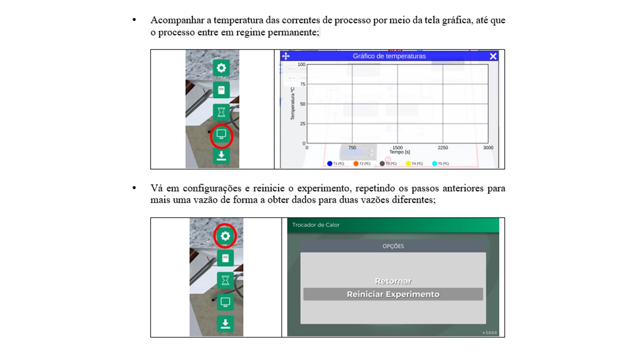
Appendix - Guidance for Performing PART 2
Detailed instructions for performing Part 2 will be provided here.